RF Physics & Electromagnetic Management
The Nature of Electromagnetic Propagation Radio Frequency (RF) management in professional audio is the study of electromagnetic waves within the Ultra High Frequency (UHF) spectrum. To master RF, one must first understand that we are not "sending sound through the air"; we are modulating electromagnetic fields. The fundamental relationship between frequency (f) and wavelength (\lambda) is defined by the speed of light (c \approx 3 \times 10^8 m/s): Wavelength = Speed of Sound (ms)/Frequency
Calculating the length of an 80Hz soundwave:
Speed of sound 343ms / 80 = 4.2m (assuming an ambient temperature of 20 degrees)
At the center of the professional wireless band (approx. 550 MHz), the wavelength is roughly 54 centimeters. This physical dimension is the most critical variable in system design. If an antenna is placed behind a metal beam or a human body, and that obstacle is larger than 1/4 of the wavelength, the signal will be significantly attenuated or reflected. This is the "shadowing" effect. In a touring environment, where the stage is a complex geometry of steel, water (humans), and electronics, understanding that the wave is a physical object that must "fit" through spaces is the first step toward reliability.
2. The Inverse Square Law and Path Loss In a vacuum, electromagnetic energy radiates spherically. The Inverse Square Law states that the power density of the wave decreases inversely with the square of the distance from the source. In practical terms, every time you double the distance between a transmitter and a receiver, you lose 6 dB of signal power. However, venues are not vacuums. We deal with "Free Space Path Loss" combined with "Multipath Interference." Multipath occurs when the RF signal reflects off surfaces and arrives at the receiver antenna at slightly different times. If the reflected signal arrives 180 degrees out of phase with the direct signal, a "null" or "dropout" occurs. This is why "Diversity Reception"—using two antennas and two independent receiver circuits—is the industry standard. The probability of a phase-related dropout occurring at two physical locations simultaneously is mathematically remote.
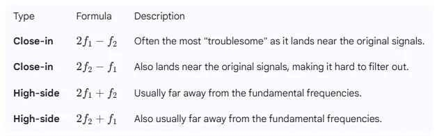
3. Intermodulation Distortion (IMD) and Non-Linearity When multiple RF transmitters (mics, IEMs) are active, they don't just exist in isolation. If two signals (f1 and f2) enter a non-linear circuit (like the output stage of a transmitter or a pre-amplifier in a distribution system), they create new frequencies. The most dangerous are the 3rd-order products: 2f1 - f2 and 2f2 - f1.
In a system with 20 wireless microphones, the number of potential IMD products grows exponentially. If a "ghost" frequency lands on a physical frequency used by another mic, it creates a "hit" or a floor of noise. Coordination software (like Wireless Workbench) uses "K-factor" math to calculate these products and ensure that the "clear" window for each mic is wider than the combined IMD products of the rest of the system.
Calculating Thirds Order Frequencies
Single-Tone Third-Order Product (Harmonics)
If you have a single input frequency (f_1), the third-order product is simply the third harmonic.Formula:f_{3rd} = 3 \times f_1 Example: If $f_1 = 100 \text{ MHz}, the third-order harmonic is 300 \text{ MHz}.
Two-Tone Third-Order Products (Intermodulation)
When two frequencies (4 f_1 and 5 f_2) pass through a nonlinear system (like an amplifier or mixer), they interact to create Intermodulation Distortion (IMD).6 These are the "products" usually referred to in RF engineering.
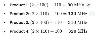
There are four primary third-order intermodulation products (IM3):
Example Calculation:If your two tones are f_1 = 100 \Freq.{ MHz} and f_2 = 110 \Freq.{ MHz}
4. Signal-to-Noise Ratio (SNR) and the Noise Floor The goal of an RF engineer is not "maximum signal," but "maximum SNR." The noise floor is the sum of all background electromagnetic energy (LED walls, lighting ballasts, local TV stations). If your noise floor is at -95 dBm and your microphone is hitting at -70 dBm, you have a 25 dB SNR, which is excellent. If you increase your transmitter power to "blast" through, you actually increase the IMD across the entire band, effectively raising the noise floor for everyone else. Engineering elegance in RF is the art of using the minimum necessary power to achieve a stable SNR.
5. Modulation Schemes: Analog vs. Digital Analog wireless uses Frequency Modulation (FM). The audio signal varies the frequency of the carrier wave. While simple, it is spectrally inefficient and susceptible to "companding" artifacts. Digital wireless (like modern high-end systems) converts audio to data and modulates the carrier using techniques like QPSK (Quadrature Phase Shift Keying). Digital systems offer a "cliff effect": the audio remains perfect until the SNR drops below a specific threshold, at which point the audio drops out completely. This is vastly superior to the "static and hiss" of failing analog systems.
Practical Lab: Coordination Logic
Tool: Wireless Workbench 7.
Objective: Coordinate 32 channels of digital wireless in a "congested" metropolitan environment.
Tasks:
Perform a "Site Survey" import for a major city (e.g., London).
Identify and manually exclude the top 3 strongest DTV stations.
Configure an inclusion group for 12 channels of IEMs (Primary Priority).
Calculate frequencies for 20 channels of Mics (Standard Priority).
Compare the "Standard" vs "High Density" results.
Daily Assessment
Math: Calculate the 3rd-order IMD products for two microphones at 520.100 MHz and 521.500 MHz.
Answer:
2 x 520.100 - 521.500 = 518.700Mhz
2 x 521.500 - 520.100 = 522.900Mhz
Theory: Explain why a 1/2 wave antenna is more efficient than a 1/4 wave antenna for a remote receiver position.
Answer:
1/4 wave antenna’s are dependant on a ground plane, and expect to be connected to a metal chassis that acts as an additional conductor. 1/2 wave antennas are a self contained system that provide its own ground making it ideal to be mounted remotely.Theoretically 1/2 wave antennas provide 3db more gain (power) and due to it being twice as long as a 1/4 wave antenna it has better appeture to intercept incoming radio waves.
Synthesis: Describe the impact of a high-resolution LED wall on a microphone system operating in the 500-600 MHz range.
Answer:
An LED is a massive array of high speed electronics. These electronics can give off spurs of high frequency interference due to the nature of the DC current required to drive the LED wall. In RF speak this creates interference and increases the noise floor making the stage a troubling RF environment.